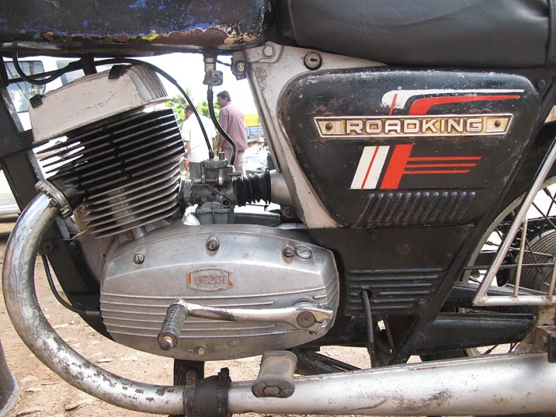
Gap Stagger Without the Superstition: Clocking Rings on a Rebuilt British Twin
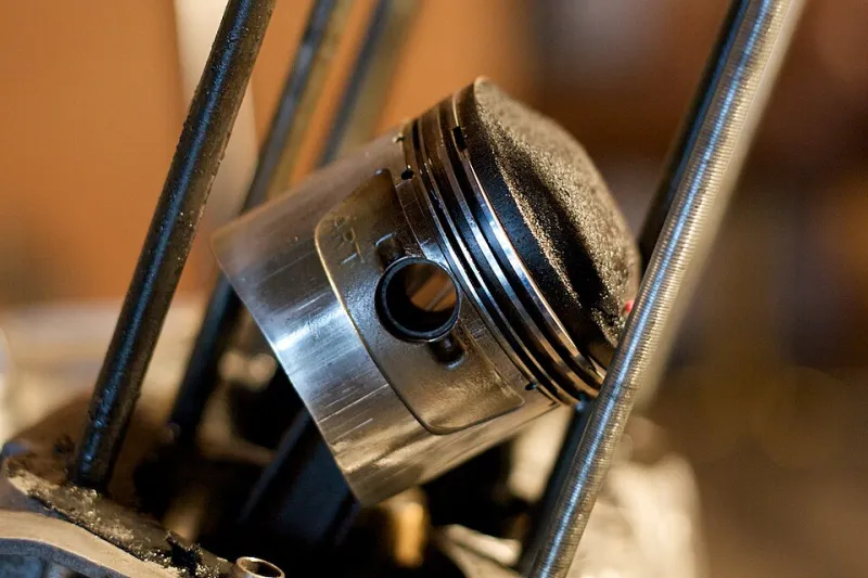
Photo: Honda CB77 Restoration, CC BY 2.0, via Wikimedia Commons
The first top end I ever built came with a free scrap of advice from a bloke selling dodgy magnetos at an autojumble: put the gaps at twelve, four and eight and you will be right. Twenty-odd years on, that same line is still doing the rounds on forums, usually posted alongside a diagram nicked from a Japanese workshop manual and a strong opinion about which way is clockwise. It is not bad advice. It is just that nobody ever says why, and once you know why, the whole business stops being mystical and becomes a small housekeeping job you can do with a paint pen.
Where the 120-degree rule actually came from
Dig out the original literature for a Triumph 650, a BSA A65 or a Norton twin and you will find a curious lack of precision. Several manuals say something along the lines of spacing the ring gaps evenly around the bore. A few say nothing at all beyond fitting the rings the right way up and keeping the markings towards the crown. The exact clock positions printed in bold in some later workshop manuals tend to be borrowed from factory practice elsewhere, or simply repeated until they looked official.
That is not a criticism. Even spacing is a perfectly sensible default. The trouble starts when a rule of thumb gets promoted to law and blokes start arguing about whether 120 degrees means 120 degrees from the gap or 120 degrees from the last one, and whether the oil ring counts.
Does clocking actually matter on a low-revving air-cooled twin?
The honest answer is: less than the internet suggests, and more than nothing. Rings rotate in service. They creep round the piston as the engine heats and cools and as the bore wears. Any stagger you set on the bench is a starting position, not a permanent arrangement. Within a few hundred miles the gaps will have migrated to wherever they fancy, which is why a strip-down of a high-mileage engine usually reveals gaps sitting in positions no builder would have chosen deliberately.
So why bother at all? Because the first few minutes are the ones that matter. A fresh bore and a fresh ring face have no oil film history and no wear pattern. If two compression-ring gaps happen to line up directly above one another on that first start, you have given blowby a straight, unobstructed road for as long as it takes the rings to settle. On an air-cooled twin that has just been rebored, with everything tight and hot and slightly nervous, that is precisely the moment you do not want a vertical chimney up the side of the piston.
Equally, you do not want a gap parked directly over a wear step or a score in the bore. It will not cause a failure, but it will let a puff of gas past exactly where you least want it while the ring is trying to bed in.
Pin axis or thrust face: pick a side and stop fretting
Here is where the arguments really get going. One camp insists the gaps should sit on the gudgeon-pin axis, at three and nine o'clock if you imagine the pin running left to right. The reasoning is that the ring is least well supported at the gap, so you move that weak point away from the thrust faces where the piston is pushing hardest against the bore.
The other camp puts the gaps on the thrust faces and argues that the pin-axis area is the hottest and least supported part of the piston, so the gap is better off in the cooler, better-lubricated region.
Both arguments have merit, and neither has been settled by anyone with a dynamometer and a fortnight to spare. On a 1960s British twin pulling maybe 5,500 rpm on a good day, with a compression ratio in the eights and a service life measured in decades rather than race weekends, the difference is unlikely to be detectable. Pick whichever scheme your manual specifies, or pick the pin-axis one if your manual is silent, and then be consistent about it. Consistency is what lets you read a future strip-down as a story rather than a puzzle.
The oil ring is where first-timers come unstuck
The compression rings are easy. The oil-control ring is where good men go quiet and start staring into the middle distance. Most British twins of the era use a three-piece oil ring: two thin rails and a corrugated expander between them. That means three separate gaps to think about, plus a joint in the expander, and the way they interact is genuinely worth getting right.
The classic mistakes are worth listing, because they all cost oil and none of them announce themselves quickly. The expander butt ends can be overlapped instead of butted, which jams the whole assembly and stops the rails from loading properly. The two rail gaps can be stacked directly on top of one another, which defeats the object entirely. A rail gap can be left sitting exactly on top of the expander joint, which is the worst of all worlds. And the expander tang, where there is one, can be missed entirely, so the ring spins freely in its groove and quietly chews the land.
There is also an old piece of folklore about never putting a gap over the gudgeon pin because of the pin-boss expansion. Treat it as folklore rather than gospel, but know that if you follow the pin-axis scheme, the oil-ring rail gaps will naturally end up away from the thrust faces, which is where you want the oil film doing its work anyway.
One thing worth saying plainly: none of this rescues a ring with the wrong end gap. Stagger is a detail on top of correct gapping, not a substitute for it.
A five-minute bench method
This is the bit worth doing properly, because it costs almost nothing and pays off years later.
Clean and dry. Wipe the bore and the piston skirt down so the paint pen will take and nothing is smeared. Rings can go on dry for this exercise; you are only setting positions, not final assembly.
Mark the crown. With a paint pen, mark twelve o'clock at the front of the piston, then three, six and nine, using the gudgeon-pin axis as your reference. A small scribed line on a clean crown works too, but paint is easier to see from above.
Fit the rings your way. Orient the compression rings per your chosen scheme, then the oil-ring expander, then the rails. Check the expander butt ends are butted and not overlapped, and that the rails sit square in the groove.
Photograph it. A phone snap straight down onto the crown, with the clock marks visible, is worth more than any note you will write afterwards. Take two, in case one is blurry.
Fill in a build sheet. On the same sheet as your torque figures and your cold ring end gaps, record each gap position and the measurement. Cylinder number, ring, position, gap size. If the engine ever comes apart again, that sheet tells the next owner exactly what they are looking at.
Then fit the barrel. Base gasket, barrel on, torque in stages as your manual says. Once it is down, the gaps are sealed in and your photograph is the only record you have.
The record is the part that actually lasts
Rings will rotate, hats will be eaten, and in five years you will not remember whether you put the second ring at eight o'clock or ten. What you will have is a photograph and a line on a build sheet. That is worth more than any argument about clockwise, and it is a great deal more use than another round of autojumble advice.